Posts

23cm Antenna progress

Image
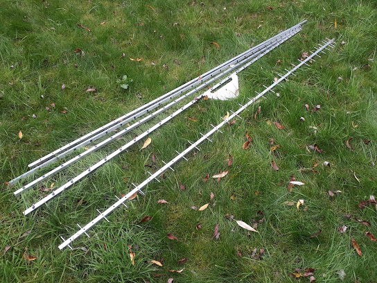
 Some 3 years (god, is it that long?  it seems it is!) I started building some antennae for 23cm based on the "usual" DL6WU formulas, JVL calculations etc. Results were not good, the antennas would not resonate where they should, the pattern was sub optimal.   Some of the early failures, with success at the front.   Numerous attempts to fix them failed.  The problem was "boom correction" .. I was using 4mm rods in either 15mm or 5/8" (15.875mm) booms, with insulators. Various rules of thumb exist on how much extra length to add to compensate for what is "hidden" by the boom cross section. I specifically did NOT want to use elements directly embedded in the boom with an electrical connection to the boom itself, as while they may work initially, as corrosion between the elements and the boom sets in, performance is variable at best.    The realisation that "just adding 75% of the boom diameter" was not going to work came through building a pro

Path Profiles on KST2YOU

Image
 In a moment of madness/boredom I added some path profiles to my KST2YOU software, available on the map simply by clicking any marker, or indeed any random spot on the map. As yet they do not include earth curvature, but they are still useful for microwave comms to give you an ide as to whether a path will work easily or may need a bit more luck.   As always, the software is at https://kst2you.bss.design/    just log in with your normal KST username/password.
Image

Datong ASP Alignment

Image
Alignment notes on the venerable Datong ASP Automatic RF Speech Processor. Note these apply to the metal box version, not the later "blue plastic box" version.   PSU Check Apply power, check consumption 15 to 20 mA  Check any of the Vs points for 6.1 to 6.2V   Master oscillator .  Check Pin 2 of  IC6 for clock, adjust L3 for roughly 60 kHz, not critical, but once set, leave it!   Modulator balance. Check TP1 (Pin 5, IC 4, or the convenient leg of the resistor near it) This is the modulator output. No audio input, select 0dB switch to minimise input noise.  Adjust VR1 and VR2 to achieve modulator balance. Repeat until  minimised, some interaction. Less than 1mV on TP1 is good.   RF Bandpass Filter Apply 1 kHz tone, 1mV to input, speech light should light. threshold is ~ 0.5mV on "LO" setting, 150 mV on "HI" setting. Set 100mV on signal generator and "LO" input, 6dB of clip Adjust  L1 for max audio output with 3kHz audio input Adjust L2 for max

Modulated Signal Source

Image
 A short project for a modulated, portable signal source, ideal as the "other end" of an antenna test range. Anyone who has tried to measure the performance of an antenna knows there are 2 halves to the problem ... detecting the signal and sending the signal.  Detecting and accurately measuring the signal is a well solved problem, the venerable HP415E is the weapon of choice.  The '415 is self-contained, battery powered and very accurate. With a simple diode detector it makes an ideal portable measuring device and has been the backbone of many professional and amateur test ranges for many decades.  The problem with the '415 is it needs a modulated signal source, 1kHz of AM is needed on a carrier of the desired frequency. There is little point having a portable detector if you have to lug 20 kilos of bench equipment out into the field and provide it with mains power to generate the test signal. To solve this, I used a cheap synthesised signal ADF4351 signal source from

24GHz LNA design

Image
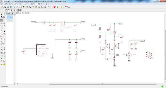
So, here are my thoughts on an LNA design for 24 GHz, inpired by Ron Schiltmans DU3T design, I thought I would try something similar. The basic concept is a waveguide input, 2 stage desgin for 24GHz,  with a CE3520K3 FET on the input, and a MMIC amplifier as the second stage.  For the second stage I plan to use an HMC341 I will include my calculations and assumptions for the design, if you can spot an error in my thoughts, I would be of course, delighted to hear from you! The circuitry on the left is a simple 3.3V regulator, feeding a ICL7660 negative voltage generator. The 3.3V is used to feed power to the MMIC amplifier and the input FET.  A simple P type FET prevents power being supplied to the front end FET before the negative voltage is present.   The  CE3520K3 was selected as it is pretty much the only real option easily obtainable from Mouser. I'd like to give you a better answer based on cost and performance, selection of matching parameters etc, but basically, it comes dow

Dish update ... pretty much there.

Image
 Finally completed the 3 little stainless steel "pucks" that form the locking arrangement for securing the dish "L Bracket" to the pan and tilt head's quick release mechanism.  Those innocuous little lumps of stainless where a pain to machine and adjust, Not something I would want to do again, although I suspect I will have to as I have 2 of these pan and tilt units!  I'll probably add some sort of trianglular brace, just to take some strain off the bolts, but, its pretty rigid as it stands. The basic sequence is tripos erected, L bracket clipped on to the pan and tilt unit. Dish hooks on to the front with the 4 prongs. Feed is inserted through the hole, big brass nut tightened up, job done.